|
Richard D. McRanie INTRODUCTION There is significant potential that an electrostatic precipitator (ESP) performance model will provide a useful mechanism for evaluating the performance of ESPs under the CAM rule. These models predict the performance of ESPs from fundamental principals and have proven to be accurate when calibrated (set up) with actual operating data. The Electric Power Research Institute (EPRI), in cooperation with several individual electric utilities, has initiated an Tailored Collaboration (TC) project to investigate the use of ESP models under CAM. RMB has been in contact with EPA throughout the rulemaking process and EPA has agreed to allow the utility industry to develop its own ESP CAM protocol for inclusion in the CAM Guidance Document. Assuming this project is successful, a "standard" CAM protocol for ESPs will save the electric utility industry a significant amount of effort and money in negotiating with the various regulatory agencies and demonstrating case-by-case protocols. The remainder of this paper is a discussion of the CAM rule, its impact on the electric utility industry and a description of the EPRI CAM project. OVERVIEW OF THE CAM RULE The CAM rule was promulgated by EPA on October 22, 1997.
It is the offspring of the fundamentally flawed proposed Enhanced Monitoring
(EM) rule which suggested an absolute demonstration of compliance with
any applicable emission standard. The proposed EM rule was so burdensome,
and impacted so many industries and very small sources that it soon became
obvious to EPA that the rule would not survive the political and technical
attacks. Consequently, the EM rule was dropped and development of the CAM
rule was reassigned from the EPA Enforcement Division to the Office of
Air Quality Planning and Standards. The CAM rule is very simple in concept but far-reaching in application. The premise of the CAM rule is that, if a control device is properly operated and maintained and has defined operational criteria and compliance criteria, then emissions will be reduced. A quote from a speech by a closely associated EPA person sums up the rule well, "Our objective is to make sure that the control device operator pay as much attention to the control device as he does to the production process. We want him to be ready for a compliance test every day." We also have to mention the Credible Evidence (CE) rule that was independently promulgated by EPA. The essence of the CE rule reads as follows: "For the purpose of submitting compliance certifications or establishing whether or not a person has violated or is in violation of any standard of this part, nothing in this part shall preclude the use, including the exclusive use, of any credible evidence or information, relevant to whether a source would have been in compliance with applicable requirements if the appropriate performance or compliance test or procedure had been performed." This simple CE rule must be kept in mind as one works through the requirements and implementation of the CAM rule. In general, CAM impacts all sources that are subject to the Title V permit program and are classified as "major sources" for any applicable emission standard. Relative to our discussion today, if the particulate emissions are greater than 100 tons/year uncontrolled, and the boiler is equipped with a control device, then CAM applies. (Obviously, boilers equipped with control devices for SO2 and NOX are also impacted but that discussion is beyond the scope of this paper.) Since virtually every coal-fired utility boiler meets the applicability definition, a considerable population of ESPs and baghouses are impacted. (Baghouse CAM approaches are also not discussed in this paper because they should be fairly straightforward.) Under the CAM rule a utility generating unit with an ESP or baghouse must:
In addition, the CAM rule requires any affected unit to have a CAM Protocol in the Title V permit that contains:
The fundamental question then becomes, how do we develop
a CAM Protocol for ESPs?
Direct Particulate Mass Monitoring Direct particulate mass emissions monitoring would obviously
be the choice if the technology was available. Unfortunately, we do not
believe this technology is ready for compliance determination purposes.
A number of different particulate mass monitors have recently been tested
by EPA as a part of the hazardous waste incinerator rulemaking. EPA used
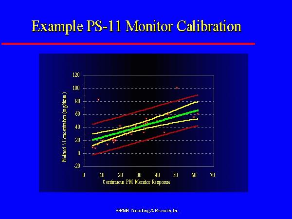
a new Performance Specification (PS-11) to evaluate the performance of
particulate mass monitors. Figure 1 shows the performance of one of the
EPA tested monitors. Obviously, the middle line through the data represent
the linear best fit of all the data. The next set of boundary lines represents
the 95% confidence interval. One must be careful to recognize that the
confidence interval tells us nothing about any individual data point. The
confidence interval lines only say that, if the identical series of tests
was repeated, there is a 95% percent probability that the second data set's
linear best fit line would lie between the confidence interval lines. Test and Cap The test and cap approach is very simple and straightforward and was the original particulate approach contemplated by the EM rule. This approach is to simply perform a compliance test and, if the control device (ESP or baghouse) showed in compliance operation, then future operation would be limited to the opacity during the compliance test plus 2%. In other words, if compliance was demonstrated at 5% opacity, future operation would be capped at 7% opacity. While this approach may be applicable to some baghouses, it would seriously compromise the ability of an ESP to use performance margin that had been purchased by the utility. Opacity/mass and ESP Power/mass Correlations Opacity/mass correlation and ESP power/mass correlation are other "compliance demonstration" techniques that have been used by utilities and states in the past. Given a consistent supply of coal and some ESP performance margin, opacity/mass correlation might be a useful approach under certain circumstances. ESP power/mass correlation does not appear to be a useful approach because the particulate collection rate in an ESP depends on the specific section of the ESP where the power is applied. The permeations and combinations are just too complex for a simple correlation to handle adequately. ESP Model Extrapolation It is believed that the ESP model extrapolation has a high probability of being a useful CAM tool for ESPs. Both EPA and EPRI have developed ESP performance computer models over the past 15 years that calculate ESP performance on fundamental principles. It has been shown many times that, when calibrated to a specific ESP, the models perform very well in predicting ESP performance changes from physical or electrical modifications to the ESP. The ESP model also has the capability of accounting for power variations in the various ESP electrical sections and for sections that are out of service. The model inherently compensates for fuel changes that influence the ash resistivity because these changes are reflected in the voltage and current relationships. In addition, using an ESP model for CAM will allow the utilization of ESP performance margin while other approaches are likely to restrict the use of margin. On the other hand, ESPs without margin will experience problems under any conceivable CAM implementation scenario, including use of a model. Another advantage of using the model is that it can be used for planning purposes. For example, one could examine the potential impact of a fuel change or evaluate the effect of additional ESP electrical sections being shorted. What has not been fully demonstrated is the reliability of the models over a wide range of ESP operational characteristics. This is the primary objective of the EPRI project. If the models are shown to have adequate "prediction range" then they will be extremely useful in the CAM rule context. The major disadvantage is that the model may be relatively expensive to set up and calibrate. It is important to understand that, even under the best of circumstances, an ESP model will not provide information sufficient for absolute compliance determination purposes. It is believed, however; that the information will be more than adequate for CAM where the criteria is "a reasonable assurance of compliance." THE EPRI ESP CAM PROTOCOL PROJECT The EPRI CAM project has been in place for over a year. The objectives of this project are to: (1) develop a demonstration test plan suitable for thorough evaluation of the ESP model capabilities; (2) conduct field demonstration tests over a range of ESP operating conditions; (3) analyze the field data with 3-4 different ESP models to evaluate the range of the models, and; (4) determine the minimum number of calibration runs required to obtain meaningful results for CAM purposes (i.e., to have a reasonable assurance of compliance). The primary activities to date have been to follow EPA rule making activities, to develop various implementation scenarios and to prepare a draft CAM protocol for ESPs. After the rule was finalized, planning was begun for field demonstration of the ESP CAM protocol. The first activity was to select a site for the field tests to demonstrate the protocol. The primary criteria for the first test site included:
After evaluating several candidate units among the project supporters, Georgia Power Company's Yates Unit 7 was chosen. The unit is nominally rated at 350Mw and is equipped with an ESP that has considerable margin and sectionalization. The allowable particulate mass emission rate is 0.24 lb/mmBtu and the normal emission rate is approximately 0.015 lb/mmBtu. This range allows considerable flexibility for testing purposes. The tests are scheduled to begin the first week in June and are anticipated to take two weeks. This is not to suggest that a model calibration for any specific unit will take two weeks. The plan is to take considerably more data than necessary during this demonstration period so that the models can be fully exercised under a wide variety of conditions. The ESP Model Calibration Process It has been shown over the past several years that the available ESP models can be calibrated to a given coal, ESP and operating condition. What is not known is the "range" of the models over a variety of conditions. For example, given adequate emissions test, particle sizing and ESP electrical data, a model can usually be calibrated to produce a perfect fit to the test data. This is done by adjusting certain fitting factors (primarily rapping reentrainment and sneakage) in the model. After calibration, the model can be used to evaluate general operating condition changes such as stack flow, inlet particulate loading, addition of plate area, loss of electrical fields and changes in ESP power. The magnitude of impact on ESP performance, either positive or negative, can be clearly seen. What has never been documented in the public domain, however, is the accuracy of these "off calibration" predictions. (Private data show that the models do a very excellent job of predicting ESP performance for plate area additions and field splits.) To meet the project objectives, a series of field tests will be performed. The test design will evaluate the two primary performance reduction modes of an ESP - complete shorting of electrical sections and reduced power in all sections caused by unfavorable fuel or flue gas conditions. All tests will be run at nominal full load. A general demonstration test protocol is shown below. This test protocol is much more elaborate than one might expect for a final CAM calibration protocol because it is designed to evaluate a broader range of conditions than would otherwise be necessary. For example, it will likely not be necessary to perform particle sizing tests to calibrate the model because coal-fired utility boilers produce similar sized ash particles and a default particle size distribution is usually satisfactory. ESP CAM Protocol Demonstration Test Plan A. The unit will be stabilized at full load with normal excess O2. 1. ESP inlet and outlet particle size distribution tests
will be performed. B. One or two ESP sections will be removed from service. (Opacity will be used as a guide for how many sections to remove. A measurable opacity increase will be needed.) 1. ESP outlet particle mass and size distribution tests
will be performed. (We can safely assume that the inlet conditions have
not significantly changed.) C. The process described in B will be repeated until 3-4
different conditions have been tested. E. Three or four replicate test conditions will be done to examine reproducibility of the ESP and boiler conditions. Data Analysis Calibrated data sets for all of the data runs described
above will be produced using 3-4 different ESP models. By evaluating the
difference in the amount of "correction" needed to produce a
calibration across the test conditions, the ability of the models to track
the varied conditions will be determined. A model prediction error analysis
will be done to determine variance in the prediction. It is probable that
a multiple parameter relationship will be discovered. The various models
will also be evaluated for ease of use and accuracy of prediction. CONCLUSIONS The CAM rule and its impact on the electric utility industry
is a "fact of life" and the industry must implement the provisions
of the rule. It is believed that an ESP performance prediction model can
have a very important role in demonstrating a "reasonable assurance
of compliance" for particulate emissions as required by the CAM rule.
The EPRI CAM Protocol project is designed to evaluate the possibility of
using an ESP model for CAM and, if successful, prepare a "standard"
protocol for inclusion in EPA's CAM Guidance Document. If the project is
successful, costs of developing site specific ESP CAM Protocols will be
significantly reduced. Figure 1
Agora Environmental Consulting |