Advances in CEMS & Flow Monitoring
J. Ron Jernigan, P.E., DEE
RMB Consulting & Research, Inc., 5104 Bur Oak Circle, Raleigh, North Carolina 27612
Charles E. Dene
Electric Power Research Institute, 3412 Hillview Drive, Palo Alto, California 94303
ABSTRACT
Since the promulgation of the Acid Rain Regulations required by the Clean Air Act Amendments of 1990, the electric utility industry has installed and certified over 1,500 new CEM systems. This paper identifies and discusses the most widely used monitoring technologies and sampling acquisition techniques. This paper will also discuss monitoring technology changes that have occurred during the past five years and the emerging CEM and flow monitoring technologies that may benefit the utility CEM user by enhanced measurement accuracy, reliability and lower maintenance cost.
INTRODUCTION
Over the past 20 years EPA has promulgated CEM regulations that currently affect almost all utility sources nationwide. During this 20-year period, the availability of more reliable CEM instruments including flue gas flow rate and moisture monitors has increased significantly. As a result of these most recent regulations, 40 CFR Part 75 (Part 75), the demand for extremely accurate and reliable CEM equipment has also increased to meet the tighter precision and reliability requirements specified by Part 75 regulations and by many states. The gas and flow rate monitors are now equipped with improved analytical techniques, enhanced electronics, programmable software capabilities, and troubleshooting diagnostics
Since early 1993 more than 1500 new continuous emission monitoring systems (CEMS) have been installed and certified to meet the requirements of Part 75 promulgated as part of EPA’s Acid Rain Program.
To assist the industry with ongoing efforts, this paper summarizes information on the types of sampling systems currently used for gaseous emissions, flow, and moisture and presents an overview of their analytical techniques and principles of operation. Examples of widely used equipment, recent technological advances, and advantages and limitations associated with each technology are discussed. Emerging technologies for gas, and flow measurements are described.
SAMPLE ACQUISITION TECHNIQUES
CEM systems incorporate one of three sample acquisition techniques: dilution-extractive, extractive (i.e., sampling without dilution of the sample gas), and in-situ. Inherent differences exist among the three sampling techniques, and thus each technique has distinct strengths and weaknesses, which must be carefully evaluated when selecting an appropriate technique for a specific application. The sample acquisition techniques chosen by Part 75 affected utility companies are presented in Table 1. The following sections address the principle of operation for the most widely used and currently available equipment, and technological advancements for each sample acquisition technique.
Table 1 - Sample Acquisition Methods Used by Part 75 CEMS
SAMPLE ACQUISITION METHODS |
% SO2 CEMS |
% NOx CEMS |
Dilution (In-Stack Method) |
76.2 |
67.5 |
Dilution (Out-of-Stack Method) |
9.3 |
10.8 |
Extractive (cool/dry & hot/wet) |
9.5 |
18.2 |
In Situ "Point" Method |
2.5 |
2.2 |
In Situ "Across-Stack" Method |
2.5 |
1.3 |
DILUTION-EXTRACTIVE SYSTEMS
Approximately 82% of the SO2 and NOx CEM sampling systems installed to meet Part 75 monitoring requirements were dilution-extractive systems. The principal reason for selecting a dilution-extractive system is due to its ability to measure flue gas pollutant concentrations on a wet basis. Part 75 requires SO2 emissions to be reported as a mass emission rate (i.e., lb SO2/hr). All flue gas flow rate measuring techniques are on a wet basis, consequently, wet basis SO2 emission data can be used more conveniently to calculate SO2 mass emission rates. Additionally, the Part 75 requirement to measure CO2 added to the convenience of using a dilution-extractive system because CO2 is measured as the diluent gas (instead of O2) in dilution-extractive systems. Dilution-extractive systems are extractive systems that dilute the sample gas with dry contamination-free dilution air to a level below the dew point of the diluted flue gas to eliminate condensation problems in the CEM system (in lieu of using a moisture condenser). The diluted sample is analyzed by pollutant and CO2 monitors operating at or near ambient concentration ranges. The most unique component of a dilution-extractive system (relative to other extractive systems) is the dilution sampling probe. There are two basic types of dilution probes, in-stack where the dilution of the flue gas is performed in the probe and out-of-stack (ex-situ).
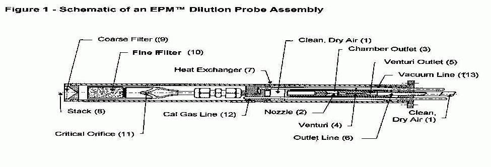
In-Stack Dilution-Extractive Probe
The in-stack probe design is equipped with coarse and fine filters for removing particulate matter from the stack gas prior to sample dilution, a quartz or glass critical orifice for flow regulation, and an air-driven aspirator and venturi for dilution of the sample gas. Approximately 88% of the dilution-extractive systems used by Part 75 affected sources are the in-stack type. Figure 1 is an example of an EPMÔ in-stack dilution extractive probe
Out-Of-Stack Dilution-Extractive Probes.
Out-of-stack dilution-extractive probes were used in approximately 10% of the Part 75 SO2 and NOx CEMS. EPM Environmental, Inc. and Sampling Technology, Inc. (STI) supplied the majority of the out-of-stack dilution-extractive probes.
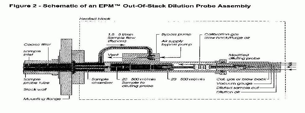
The EPMÔ out-of-stack device uses the same basic dilution-extractive sampling technology as the in-stack dilution-extractive probe, with the following differences. This system is designed to constantly heat the sampling assembly, and all critical parts are mounted out of the stack for quick access and easy maintenance. Figure 2 is a schematic of an EPMÔ out-of-stack dilution-extractive probe.
The working principle difference is, undiluted stack gas is continuously drawn through the sampling probe tube into the sampling chamber by a by-pass pump at a rate of 1.5 to 15 liters per minute. A vent in the sampling chamber ensures a constant flow of "fresh" stack gas through the chamber. The dilution probe draws a small sample of the gas out of the chamber through a sampling tube at a flow rate determined by the critical orifice of the probe. The operation of the dilution-extractive probe at this point is the same as previously described.
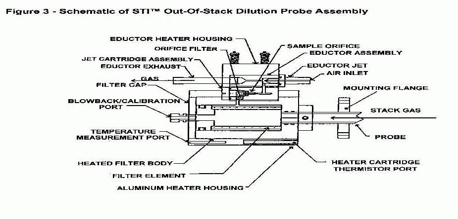
The manufacturers of these probes advertise that their heated out-of-stack dilution probe design eliminates the need for temperature compensation for stack gas temperature fluctuations. EPM recommends its out-of-stack dilution probe for flue gas applications after wet scrubbers or high particulate matter loading. Figure 3 is a schematic of a STIÔ out-of-stack dilution-extractive probe assembly. The general operation of this dilution-extractive probe assembly consists of three modes: sampling, blowback purge, and calibration mode.
Dilution Air-Cleanup System
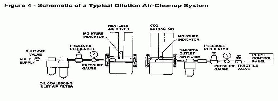
Dilution-extractive probe systems require a constant source of contamination free dilution air. The air supply should be dry (-20° to -40° F) and delivered at 90 ± 10 psig. Additionally, the dilution air should be free of oils, particulates, CO2, NOx, and SO2. A plant’s compressed air system does not generally provide dilution air to the needed specification. Therefore, an additional air-cleanup system is required. In Part 75 dilution-extractive CEMS the air-cleanup system is the critical component of the dilution-extractive system. Figure 4 is a schematic of a typical dilution air-cleanup subsystem.
Compressed air either from the plant's compressed air supply or from a dedicated air compressor is first filtered for particulates, then liquid and oils condensate by a coalescing filter. Oil removal is necessary to prevent the contamination of silica gel or other drying agents in the heatless air dryer. Additional drying of the dilution air is performed by a heatless dryer that can dry the air to approximately -100° F. The CO2 extractor utilizes two columns with different adsorbent materials to adsorb any CO2 in the dilution air. Some air cleaning systems may add a CO to CO2 converter (not shown in Figure 4) before the CO2 extractor if their analyzers respond to interferences from CO. A charcoal filter trap (not shown in Figure 4) may also be added to remove any hydrocarbons that may be in the dilution air. An additional desiccant dryer (not shown in Figure 4) may be added to provide additional moisture removal. A submicron filter removes any particulates that may be released from the upstream desiccant traps.
Gas Sample Dilution Ratios
Dilution ratios typically range from 50:1 to 300:1. The dilution ratio most widely used by Part 75 sources is 100:1. The sample gas flow rates from the various dilution probes range from 50 to 300 ml/min. Two criteria are used to determine the desired dilution ratio: (1) the analyzer span range must correspond to the diluted sample gas concentration, and (2) the ratio must be selected to ensure that no condensation occurs in the sample line at the lowest possible ambient temperature.
Sample Umbilical Bundles
The sample umbilical bundles of dilution-extractive systems usually consist of four to six separate lines; one Teflon® line for sampling, a second Teflon® line to deliver calibration and purge gases to the probe, a third line to deliver dilution air to the probe, sometimes a fourth line to monitor vacuum in the probe, and sometimes one or two "spare" Teflon® lines. The spare lines are often used for diagnostic purposes (e.g., resolving or isolating leak problems) or for backup monitoring equipment. The diluted gas sample line should be at least 3/8 in. in diameter and, if the overall sample line length exceeds approximately 350 feet, a 1/2-in. sample line may be needed to reduce the pressure drop between the probe and the monitors. High pressure drops may prevent adequate sample flow to the monitors or cause condensation problems. Using a 1/2-in. sample line over long distances, however, can significantly impact response times (response times for a 3/8-in. line are typically 15 seconds for every 100 feet) such that timesharing a CEM system between two locations may be precluded. Heat traced umbilical bundles are required only in very cold ambient conditions or when dilution ratios less than 25 to 1 are used in climates subject to below freezing ambient conditions in the winter.
Dilution-Extractive Probe Technological Advances During The Acid Rain Program
The data availability requirements for Part 75 CEMS forced CEM system suppliers and utility CEMS users to improve the dilution-extractive system’s reliability. Reliability improvements include, improved dilution air cleaning systems, probe heat exchangers (in-stack and out-of-stack) that compensate for varying gas temperatures, improved automated purging and calibration, improved diagnostic equipment/procedures, and the use of freeze-protected sample lines in climates that have winter ambient temperature that drop as low as 0° F.
At least three out-of-stack dilution probes exist that house the filter, inertial separator, orifices, and aspirator system outside of the stack or duct environment in a temperature controlled chamber. Housing the filter and dilution components outside of the stack facilitates their maintenance because the probe does not have to be removed. These systems can tolerate a wider change in effluent temperatures, and the out-of-stack filter can be fabricated from materials with lower temperature ratings. Potential disadvantages of the out-of-stack dilution probe include (1) the flue gas flow rate through the probe and inertial separator is typically 50 to 200 times greater than in the stack probe, and (2) evaluating the need for maintenance can be more difficult with some out-of-stack filter designs.
EXTRACTIVE SYSTEMS (NON-DILUTION)
Historically extracting, transporting and conditioning a hot, wet, particulate matter-laden flue gas for analysis has been problematic. This in part explains why only 14% of the utility companies installing SO2 and NOx CEMS to comply with Part 75 monitoring requirements chose non-dilution extractive sampling systems. Non-dilution extractive systems are classified as "cold/dry" or "hot/wet" systems.
COLD/DRY NON-DILUTION EXTRACTIVE SYSTEMS
Typical cold/dry non-dilution extractive systems have four common subsystems: (1) effluent/CEM system interface, (2) sample transport, (3) moisture removal, and (4) pollutant and diluent analyzers.
Effluent/CEM System Interface
The effluent/CEM system interface typically consists of a corrosion resistive rigid probe, positioned at a representative location in the effluent. A coarse filter made of sintered stainless steel or porous ceramic materials is used to filter out particulate matter greater than 10 to 50 µm. Historically the coarse filter was located at the probe inlet; however, some current designs have the filter positioned out of the stack for ease of maintenance.
Sample Transport System
The sample transport system begins at the junction between the probe and the sample transport line, usually positioned just outside the stack or duct. Sample transport systems consist of heated sample transport lines and a mechanism such as a pump to move the gas sample. The sample tubing is usually a non-reactive material such as Teflon® and the parts of the sample pump exposed to the flue gas are coated or fabricated from non-reactive materials. The sample pump must be designed so no lubricating oil can contact and contaminate the sample gas and no air in-leakage occurs. The most common types of pumps to meet these specifications are diaphragm and ejector pumps.
Sample Moisture Removal System
The third component, the sample moisture removal system, provides a clean, dry, interference-free sample to the analyzers. Two moisture removal methods were primarily used by Part 75 sources in sample moisture removal systems: condensation and condensation/permeation.
Condensation Systems
Condensation systems rapidly cool the sample, thereby condensing sample moisture. The condensed moisture is trapped and periodically removed from the condenser assembly. To avoid absorption of the target gases by the condensed liquid, precautions are usually taken in designing condensers and traps that minimize contact between the condensate and the cooled sample.
Two basic techniques are generally employed to prevent the trapped condensate from contacting the target gases. The first and most common approach uses a standard compressor-type refrigeration unit, and the other is the thermoelectric plate chiller, a solid-state unit with no moving parts.
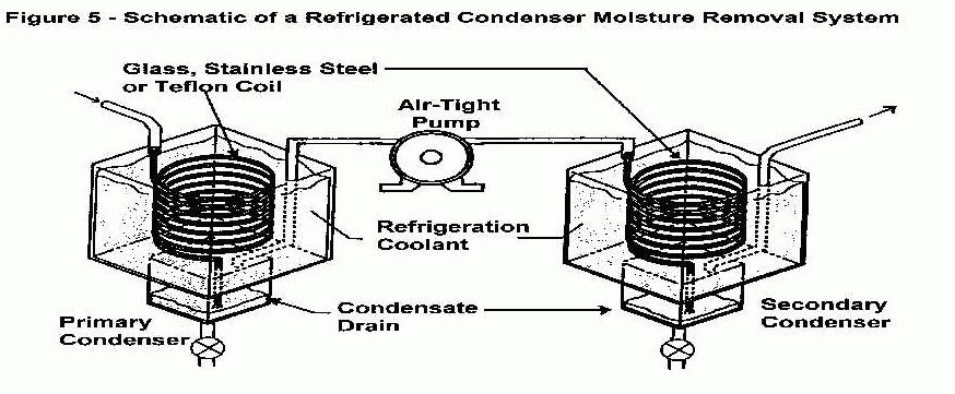
Refrigeration Condensers
Refrigeration condensers for moisture removal are the most common system used by Part 75 non-dilution extractive CEMS. Figure 5 presents a schematic of a typical dual condenser system. This method provides secondary moisture removal because flue gas under pressure will condense to a greater degree than the flue gas under vacuum. The limitations of condenser systems are that it generally requires a complex valve and plumbing system (which often requires a high level of maintenance) for adequate moisture removal.
Thermoelectric Chillers
Thermoelectric (TE) chillers work on the "Peltier effect" principle and TE chillers are sometime called Peltier chillers. The most commonly used TE chillers work as flat plate heat exchangers and cool the sample gas to a dew point temperature that causes the moisture in the sample gas to condense on the TE chiller plenum walls and then drain from the system. Anarad, Inc. was the leading supplier of non-dilution extractive NOx CEMS and used TE chillers in their CEMS. One utility using TE chillers added a permeation dryer after the TE chiller for backup and additional moisture removal
Permeation Dryers
Permeation dryers were used in conjunction with refrigerated condensers for several Part 75 sources to provide additional moisture removal in the event of moisture carry over from the upstream condensers. This technique is based on the selective permeability of water through a membrane. Permeation occurs continuously as moist stack gas flows in one direction through the dryer, while dry purge air flows countercurrently on the other side of the membrane.
Hot/Wet Non-Dilution Extractive Systems
For hot/wet systems, the moisture is not removed from the flue gas sample prior to entering the analyzers. Less than 2% of the total Part 75 SO2 and NOx CEMS were hot/wet systems. Perkin Elmer manufactured the only hot/wet analyzers. The analyzer called the Model MCS-100 could be configured to analyze data cold/dry by installing a moisture removal systems and the measurement cell would be heated to only 100°C (121°F) instead of 185°C (365°F) as required by the hot/wet measurement cell. The majority of the Perkin Elmer MCS-100 analyzers used for Part 75 sources were configured for cold/dry operation.
Extractive Probe System Technological Advances During The Acid Rain Program
Only limited technological improvements have been made to extractive systems, which have been used extensively over the past 10 years. Probe materials and designs have improved; some probe materials and coatings currently available are more resistant to corrosion, while other materials can withstand temperatures exceeding 3000° F. Other advances include (1) the availability of easily spliced heated sample lines and (2) the use of secondary conditioners to ensure that particulate matter and moisture removal are adequate for those monitors that measure gas concentrations on a dry basis. Historically, only a limited number of extractive monitors measured gas concentrations on a wet basis; however, only Perkin Elmer supplied a (single) monitor that operates on a wet basis for Part 75 monitoring requirements. This single monitor can measure concentrations of up to eight gases, including moisture and ammonia.
Although these improvements have enhanced the performance of extractive systems, various changes in typical operating and maintenance procedures have had an equal or greater impact on accuracy and reliability. During approximately the first three months of operation, many operators discover that "anticipated" operating and maintenance procedures must be altered to optimize CEM system performance. For example, minimizing sample gas flow rate, providing more filtration at the probe tip, and lengthening purge cycle times might result in optimum monitor reliability and accuracy at one location, while maximizing flow rates, minimizing probe tip filtration, and operating the heated sample line at elevated temperatures might produce the best results at another location.
IN-SITU SYSTEMS
As the name implies, in-situ gas monitoring systems are designed to measure gas concentrations directly in the stack or duct, without extracting samples for external analysis. Two types of in-situ monitoring systems are currently in use. The first is an across-stack (or path in-situ) system that analyzes the effluent passing by a specific "line of sight" of the monitor, typically ranging from a few feet to the full distance across the interior stack or duct diameter. Approximately 2.5% of the SO2 CEMS in the Acid Rain Program are path in-situ type. All of the path in-situ CEMS are OPSISÒ systems that measures flue gases by differential optical absorption spectroscopy (DOAS). The OPSIS Model ER 070 emitter and receiver are typically used for stacks less than 15 feet in diameter and the Model ER 080 transceiver is typically used for stacks greater than 15 feet in diameter. EPA distinguishes between path and point analyzers by the percentage of the stack or duct diameter (or equivalent diameter for non-circular ducts) represented by the measurement path. Instruments that measure gas concentrations along a path less than or equal to 10% of the diameter are point analyzers. If the measurement path is greater than 10% of the equivalent diameter, the instrument is considered a path analyzer.
The second is a point in-situ instrument, which analyzes the effluent at one specific point or along a short path in the stack or duct. Approximately 2.5% of the SO2 CEMS in the Acid Rain Program are in-situ point type. All point in-situ systems are Monitor LabsÒ CEMS that measure flue gas by UV (ultraviolet) Second-Derivative Spectroscopy. Lear Siegler, Inc.'s Model SM 800, introduced this technology over 20 years ago.
In-Situ Technological Advances During The Acid Rain Program
Few significant changes in in-situ technology have been made in the past 10 years, with the exception of some improvements to the electronic components and the capability of OPSISÒ across-stack (path) in-situ monitors to accept calibration cylinder gases for daily and audit calibration checks. Point in-situ monitors have had the capability to accept calibration cylinder gases for many years.
GASEOUS CONTINUOUS EMISSION MONITORS
The following subsections provide a brief overview of the SO2, NOX, CO2, and O2 monitors that were most widely used by utility Part 75 sources and their principles of operation.
SO2 Monitors
SO2 monitoring technologies are well established and only incremental advances have been made in the past five years of the Acid Rain Program. A brief overview of these technologies is given.
Fluorescence Monitors\
Fluorescence SO2 analyzers, both pulsed and continuous ultraviolet (UV) light source type, was originally manufactured for ambient air monitoring. Ambient air SO2 concentrations are in the parts per billion (ppb) range, and these units operate well at that low concentration. Because the fluorescence technology was a proven technology in low concentration ranges and was well-matched for dilution probe applications, it was chosen by approximately 85% of the Part 75 sources with dilution-extractive systems for monitoring SO2. Presently, several companies manufacture or use continuous or pulsed-fluorescence analyzers for SO2 monitoring. However, one manufacturer (Thermo Environmental Instruments) of pulsed-fluorescence analyzers supplied 65% of the SO2 analyzers and another manufacturer (Monitor Labs) of continuous-fluorescence analyzers supplied 15%.
Problems associated with quenching and other interferences have been reduced through advances in optical filtering. This precaution is not necessary when fluorescence monitors are used in dilution-extractive CEM systems with a dilution ratio greater than approximately 20:1, because the quenching effect of O2 in the dilution air dominates and is taken into account during calibration. However, using calibration gases containing approximately the same O2 and CO2 concentrations as the flue gas is recommended when fluorescence monitors are used in extractive CEM systems to minimize quenching.
Since the beginning of the Acid Rain Program, most of the vendors are now marketing microprocessor-based electronics for these monitors that enhance performance and overall reliability.
UV Spectrophotometric Monitors
Several manufacturers offer UV and one (Monitor Labs) offers second-derivative spectroscopic UV SO2 monitors for in-situ and extractive applications. UV type SO2 monitors have proven to be reliable instruments, and as with many other monitoring systems, electronic components (e.g., for optical contamination and lamp current compensation) have been improved over the past 5 years. Because the UV type SO2 monitors were either used in extractive or in-situ CEM systems, less than 15% of the Part 75 SO2 analyzers were UV type.
NOX Monitors
Typically, chemiluminescence, UV, or infrared (IR) monitors are used for monitoring NOX. Recent advances, particularly for chemiluminescence monitors, are noted in the following brief overviews of these long-established monitoring technologies.
Chemiluminescence Monitors
Approximately seven different chemiluminescence monitor vendors are used by Part 75 sources for NOX monitoring. These monitors have been installed and operated at utility sites for years and have a proven performance record. Approximately 95% of the Part 75 NOx monitors were chemiluminescence monitors. Four analyzer manufacturers supplied 85% of all chemiluminescence monitors; Thermo Environmental Instruments (65.6%), Monitor Labs (7.3%), Columbia Scientific, Inc. (6.7%), and Anarad, Inc. (5.3).
As with NO2 monitors, several of these monitors now incorporate a microprocessor, enabling the operator to check certain monitor operating parameters, perform calibrations automatically, and perform numerous diagnostic functions. If ammonia interference is a potential problem, catalytic converters are available that will convert NO2 to NO without converting ammonia to NO. Essentially all chemiluminescence monitors incorporate a high-vacuum sample chamber to minimize quenching (absorption of the fluorescent light by other molecules).
Chemiluminescence monitors do have some drawbacks, however. The catalytic converters must be replaced periodically (usually about once every six months for extractive systems and two to five years for dilution-extractive systems) to ensure complete conversion of NO2 to NO, and the capillary tubing used to regulate sample by-pass and ozone flow rates can become plugged without proper gas conditioning.
UV Spectrophotometric Monitors
Several vendors offer UV photometric and second-derivative spectroscopic analyzers for monitoring NOX. As with the chemiluminescence monitors, UV monitors have been used to monitor NOX emissions at numerous utility sites prior to the Acid Rain Program, however, less than 5% were used for Part 75 NOX monitoring. UV photometric analyzers require sample filtering to remove particulate matter and sample conditioning or heated sample cells to maintain the sample gas temperature above the dew point. Various design modifications and improvements to the electronic components (e.g., isolating the electronic and optic components from the sample cell) have been implemented.
CO2 Monitors
Essentially all CO2 monitors use IR-based technologies to detect CO2. Either non-dispersive infrared (NDIR) or gas filter correlation (GFC) technology is used. California Analytical Inc. and Thermo Environmental Instruments supplied approximately 77% of all CO2 monitors used for Part 75 monitoring. California Analytical Inc. who offers the NDIR technology supplied 46% of the CO2 analyzers. Thermo Environmental Instruments who offers the NDIR GFC technology supplied 31% of the CO2 analyzers. Thermo Environmental Instruments experienced problems with leaking GFC cells in numerous analyzers during the early stages of the Part 75 program. The problem causing the leaks (faulty cell window epoxy) was found and corrected.
As with other types of IR monitors, these monitors are subject to moisture and particulate matter interference, however, in dilution-extractive systems these interferences have been negligible. Except for the addition of some microprocessing capabilities and digital electronic components, no significant improvements have been made in recent years.
Before the Acid Rain Program, CO2 monitors were generally considered to be less reliable and less accurate (for the concentration ranges typically observed in flue gas) than O2 monitors. When using a dilution-extractive CEM system, however, the relative differences, advantages, and limitations between CO2 and O2 monitors are not an issue. A CO2 monitor must be used to determine diluent concentrations for a dilution-extractive CEM system and CO2 emissions must also be reported.
O2 Monitors
Approximately 78% of the Part 75 O2 Monitors are electrocatalytic oxygen analyzer and the remaining Part 75 O2 are primarily paramagnetic monitors. These monitoring technologies have been used for many years and provide reliable O2 emissions data. No known technological advances have been made in the past five years with these two O2 monitoring technologies.
FLUE GAS FLOW MONITORING TECHNIQUES
Most commercially available flue gas flow monitors operate using one of four principles for measuring velocity and volumetric flow: ultrasonic pulse detection, differential pressure, thermal detection (convective cooling), and audible acoustic detection. The four varieties of flow monitors are stack or duct mounted and operate as a component (including a microcomputer, pressure transmitters, and temperature transmitters) of a system. Other types of flow monitoring systems are available: fan efficiency, and infrared detection, but these two techniques have yet to be used by Part 75 sources, therefore, sufficient data are not available to evaluate their performances. These techniques will be discussed later in the emerging flow monitoring technology section.
Ultrasonic Flow Monitors
Approximately 63% of all flow monitors used in the Acid Rain Program are ultrasonic type monitors. Four manufacturers supplied ultrasonic flow monitors for the Acid Rain Program, with one (United Sciences Inc.) of the manufacturers supplying 84% of the ultrasonic flow monitors.
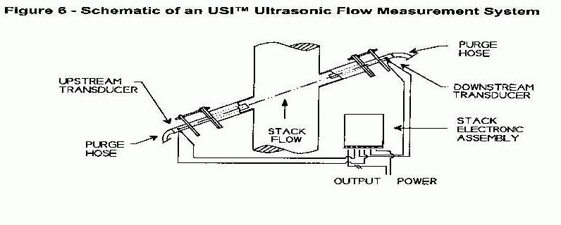
Principle of Operation
The volumetric flow rate of stack gas is measured by transmitting ultrasonic pulses across the stack in both directions (see Figure 6). The tone pulses are accelerated or retarded due to the gas velocity in the stack. The time required to traverse the distance of the stack traveling with and against the flow is a function of the sound velocity and the effluent velocity. Stack flow can be calculated based on the difference in the times required to traverse the stack in both directions. The ultrasonic pulses must traverse the stack or duct at a minimum angle of 10 degrees; however, traverses between angles of 40 and 70 degrees tend to provide the best results, as long as the traverse path length is not so long that the ultrasonic pulses become difficult to detect.
Differential Pressure Flow Monitors
Approximately 28% of all flow monitors used in the Acid Rain program are differential pressure type flow monitors. Three different types of commercially available flow monitoring devices are based on measuring differential pressure: S-type pitot tubes, the Fechheimer dual-manifold pitot probe, and annubars. The principles of operation, which differ somewhat among these three types of flow monitoring devices, are discussed in the following paragraphs.
Principle of Operation
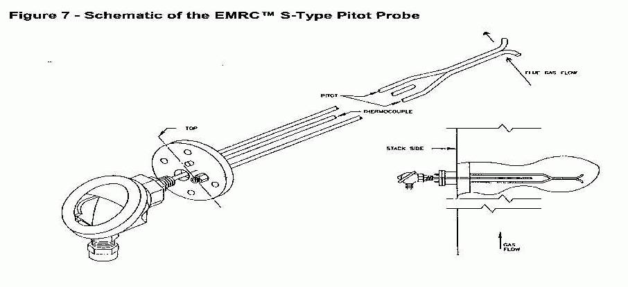
The S-type pitot tube is designed after the Stausscheibe or reverse type pitot tube as described in Method 2 in Appendix A to 40 CFR Part 60. The probe is constructed of two in-line tubes. The sampling point of the probe consists of two opposing open faces perpendicular to the traverse axis. A side view of the probe resembles two stacked tubes with the ends tapered away from one another and the openings planed parallel to the horizontal axis. Several probes are required for multipoint monitoring. The position and number of points are determined using Method 1 in Appendix A to 40 CFR Part 60. The multipoint averaging is performed in a pitot manifold and a differential pressure transmitter registers the averaged pressures. Approximately 58% of all differential pressure type flow monitors in the Acid Rain Program are the S-type pitot tube design and are supplied by one manufacturer (EMRC). This continuous flow rate monitoring technique has been used by industry for many years for mass emissions monitoring. Figure 7 presents a schematic of the S-type pitot.
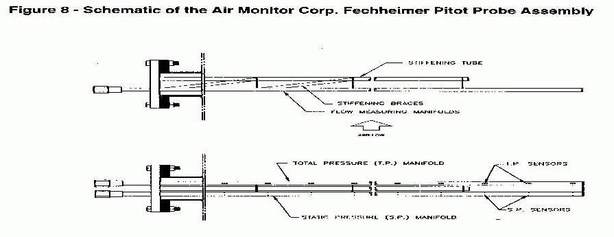
The Fechheimer pitot probe consists of flow sensors mounted on two multipoint averaging manifolds. Figure 8 presents a schematic of the Fechheimer pitot probe assembly. The probe design consists of two manifolds (tubes) welded together with a truss plate. The truss maintains a distance between the manifolds in a plane perpendicular to the flow and the stack wall. One manifold averages multiple points of impact pressure, and the other averages multiple points of wake pressure. The impact and wake pressure averages are registered by the flow transmitter. This technology is used in numerous gas flow monitoring applications other than flue gas. Approximately 31% of all differential pressure type flow monitors in the Acid Rain Program were the Air Monitor Corporation's Fechheimer pitot probe and were supplied by one manufacturer.
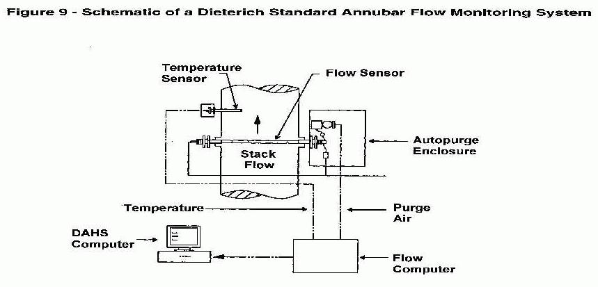
The annubar flow monitoring technology is a multipoint, dual-chambered probe. The probe averages multiple in-line (impact and wake pressures) sample points across the stack diameter (Figure 9).
The position and number of points are typically determined using Method 1 in Appendix A to 40 CFR Part 60. The interior of the probe consists of tubes within a tube. The exterior tube shrouds two averaging changer tubes. The inner tubes consist of the impact differential pressure chamber and the wake differential pressure chamber. Precision pressure points are tapped through the exterior tube into the inner tubes. The pressure registered at the flow transmitter is the average across the stack. Although this technology and its manufacturer (Dieterich Standard) have been around for many years, using this technology for many airflow monitoring applications, only 11% of all differential pressure type flow monitors in the Acid Rain Program are annubar type probes.
All of the differential pressure flow rate systems include an electronic, flow-indicating transmitter that receives pressure and temperature signals from the stack, calculates the exhaust gas flow rate, and automatically performs electronic drift checks and system purging.
Thermal Flow Monitors
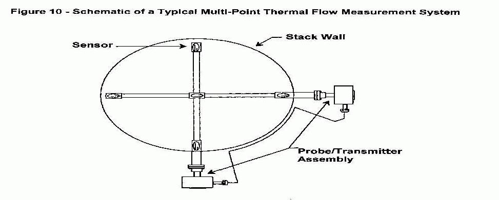
Approximately 8% of the flow rate monitors installed for Part 75 flow rate monitoring were thermal flow monitors. Two manufacturers (Kurz Instruments and Sierra, Inc.) supplied these monitors.
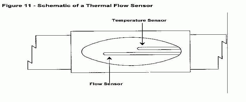
Principle of Operation
Thermal flow monitors measure the electric power required to maintain a constant temperature of approximately 75 to 100ºF above the exhaust gas temperature in a flow sensor. Figure10 and Figure 11 are schematics of typical thermal flow systems.
The monitors are available for both single-point and multipoint analysis, and non-sensing components of the systems can be constructed from various corrosion-resistant metals.
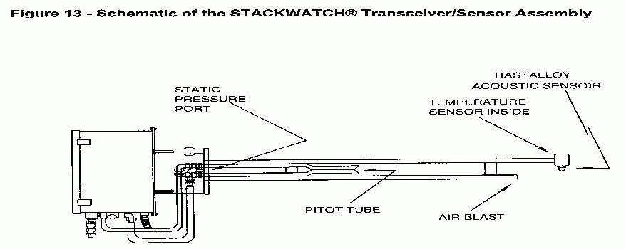
Audible Acoustic Flow Monitors
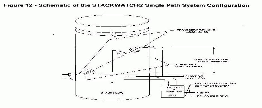
One manufacturer (Scientific Engineering Instruments) supplies a hybrid flow monitoring system consisting of acoustics, thermocouples, static pressure sensor and pitot tubes. This technology called STACKWATCH® is used in approximately 21 (2% of total) Part 75 flow monitoring systems.
Principle of Operation
Audible Acoustic technology uses sound waves much like the ultrasonic technology for measuring flow rate.
There are several distinct differences between the audible acoustic and ultrasonic technologies used for flow measurement. The primary difference is that the sound waves used in the acoustic technology are in the mid audio range (less than 10 KHz) which is well below the high frequency ultrasonic band. Other distinct differences are:
Figure 12 and Figure 13 presents schematics of this technology.
MOISTURE MONITORS
For many years, continuous monitoring equipment capable of detecting moisture has been commercially available; however, prior to the promulgation of 40 CFR Part 75, electric utilities did not have any need or requirement to monitor boiler exhaust gases for moisture content. With the promulgation of Part 75, moisture monitors became necessary components of certain CEMS and, for the first time, were subject to ongoing "EPA-type" QA/QC performance requirements. Moisture monitoring became an important aspect of the compliance monitoring efforts for utilities that use dry extractive pollutant and diluent analyzers in conjunction with flow monitors (which provide measurements on a wet basis) to calculate and report SO2 mass emissions rates (lb/hr). The following paragraphs provide an overview of moisture monitoring technologies and a discussion of the advantages and shortcomings of commercially available equipment.
Principle of Operation
Two general approaches can be used to determine flue gas moisture content: (1) a direct moisture measurement approach or (2) an indirect calculation approach which uses O2 measurements made on wet and dry basis to determine moisture content. Monitors based on two analytical principles, nondispersive infrared (NDIR) and polarography are available for direct determination of moisture. NDIR moisture monitors and polarographic moisture monitors operate on the same basic principles as NDIR and polarographic pollutant monitors. It should be noted that some of the direct moisture measurement devices require a diluted sample. In these cases, a small portion of the extracted sample has to be diluted with clean dry air prior to analysis. Other direct measurement devices maintain a heated sample throughout system by using heated lines, pumps and detectors.
Indirect moisture methods measure the concentration of a sample gas constituent (typically O2) on a wet basis and then on a dry basis. The percent difference in concentration between the wet and dry measurements is used to calculate sample gas moisture content. In many current applications, for example, flue gas O2 content is determined on a wet basis using a ZrO2 analyzer before the gas is passed through a moisture removal system. After moisture removal, flue gas O2 content is measured on a dry basis, and the moisture content of the sample gas is calculated. Note that the ZrO2 cells are always heated to very high temperatures and, consequently, tend to work well for wet basis measurements. The dry O2 measurements are then typically obtained using another ZrO2 or paramagnetic analyzer.
Moisture Monitoring Equipment
At least six different NDIR moisture monitors and at least one polarographic moisture monitor are commercially available for direct determination of moisture. Several vendors offer monitoring equipment for indirect moisture determination. For a typical extractive system (i.e., a system that monitors SO2, NOX, and O2 on a dry basis), only one additional monitor (e.g., a direct measurement device or a wet-basis O2 analyzer) must be added to the system in order to determine moisture content.
CEMs Technological Advances During The Acid Rain Program
The technological advances in CEMs have been primarily electronic enhancements and modular construction of monitors. The major CEM suppliers generally now offer the following technological advances.
EMERGING CEMS TECHNOLOGIES
The CEMS monitoring technologies used by the electric utility industry has not changed very much in the past 20 years. Although several new monitoring technologies have emerged in the past several years, the electric utility industry has mainly stayed with time proven CEMS technologies. More than 95% of the Part 75 CEMS are comprise of multiple single analyzers (i.e., one analyzer for each gas to be measured). Generally, the initial Part 75 CEMS bid specifications required strict CEM data availability guarantees from the CEM system integrators. Accordingly, the CEM system integrators chose multiple single analyzers for their CEM systems because it provided them the opportunity to supply the most reliable analyzers for the different gases to be monitored. The CEM system integrators and the utility CEMS user believe that because the multi-gas analyzers are generally more complex in design and operation, the diagnostic and repair time may be greater than that required for single analyzers. Additionally, missing data substitution would be required for several gases in the multi-gas analyzer when the analyzer is taken out of service for preventative maintenance and repairs. The potential cost penalty for missing data substitution for CEM systems with low data availability is a major concern for the utility CEMS user.
Following the Acid Rain CEM program, the requirement to measure air toxics, in sources other than the electric utility industry, and demand for "low-cost" CEM systems by small air emission sources has been the major driving force for emerging CEM technologies. These emerging technologies include, but are not limited to; Fourier transform infrared (FTIR) analyzers, photoacoustic, tunable diode laser infrared (TDIR) spectrometers, mass spectrometers, and micro-sensor technology are among the developmental instruments available or becoming available for monitoring flue gas constituents.
The electric utility’s acceptance of emerging flue gas flow rate monitoring technologies was very different from gas CEMS. This is mainly due to the utility industry having little or no experience with flow rate monitoring prior to the Acid Rain Program; therefore, the utility industry approached all flow rate monitoring technologies as emerging technologies. Current emerging flow monitoring technologies not used by Part 75 sources include infrared flow monitors, and fan efficiency devices.
Emerging Gas Monitoring Technologies
The following gas monitoring technologies discussed may be used in the future by the electric utility industry. Several of the technologies are currently used by other industry CEMS users.
Fourier Transform Infrared Analyzers
FTIR analyzers operate on the general principle of spectrophotometric analysis. The spectrophotometer produces an IR spectrum consisting of a wide range of absorption wavelengths enabling a single instrument to monitor up to eight gases simultaneously during each reading cycle. The FTIR monitor uses an interferometer as an optical discriminator to quickly scan for compound-specific IR absorption wavelengths. The interferometer contains a stationary mirror and a movable mirror, both of which are at an equal distance from the beam splitter when measurements begin. As the movable mirror tracks away from the beam splitter at a constant velocity, it passes through positions where the beam of light from the IR source is partially reflected to the stationary mirror at a particular position and relayed to the tracking mirror at another particular position. As the beams reflect and return to the beam splitter, they interfere. The light is then partially reflected and partially transmitted once more. The resulting interference causes the intensity of the individual beams passing to the detector to vary depending on the difference of the path of the beams. The resultant interferogram provides all the data necessary to create an infrared spectrum. By applying the Fourier transform equation, the readings are changed from frequency to intensity, which corresponds to individual gas concentrations within the sample gas.
FTIR-based extractive CEM systems for measuring SO2, NO2, NO, CO2, CO, CH4, and other gases are available from several manufacturers; however, at this time these systems have not been selected for Part 75 CEM systems. In general, these FTIR systems include a (1) probe constructed of materials suited to the effluent conditions; (2) heat-traced sample line; (3) conditioning unit, including filters; (4) condenser unit; and (5) microprocessor-based control unit.
Moisture and particulate matter are major interferences for these monitors that the manufacturers of these systems are still trying to eliminate. The monitors can be used downstream of a conditioning system that removes particulate matter and water vapor, but even after a conditioning system, some compensation for moisture and particulate matter interference may be required
Photoacoustic Spectroscopy
This measurement principle is a form of infrared spectroscopy. Photoacoustic infrared spectroscopy (PAS) offers a high sensitivity than conventional infrared spectroscopic techniques. The phenomenon know as the photoacoustic effect is the emission of sound by an enclosed sample on the absorption of chopped light.
When a particular gas is irradiated with light, it absorbs some of the incident light energy. The amount of energy it absorbs is proportional to its concentration. The absorbed light is immediately released as heat and this causes the pressure to rise. When the incident light is modulated at a given frequency, the pressure increase is periodic at the modulation frequency. Pressure waves, or sound waves as they are commonly known, are easily measured with a microphone. They are audible if their frequency is between 20 Hz and 20 kHz. The intensity of the sound emitted depends on a number of factors; the nature and concentration of the substance and the intensity of the incident light. The selectivity which can be achieved in spectroscopy is due to the fact that substances absorb light of specific wavelengths which are characteristic of that substance. The fundamental difference between PAS and conventional infrared transmission spectroscopy is PAS measures directly the sound energy emitted when gas molecules absorb the light in the measurement cell. The conventional method measures the light energy transmitted through the measurement cell.
A multi-gas PAS monitor manufactured by INNOVA Air Tech Instruments in Denmark is marketed by California Analytical Instruments, Inc. This monitor has an optical filter carousel that can measure up to 5 gases and moisture. This analyzer is designed for low level gas emissions, and can be used with a dilution probe much like other low concentration analyzers. A special optical filter is permanently installed in the filter carousel that allows water-vapor contribution to be measured separately during each measurement cycle. Know interference gases can be compensated for by installing an optical filter to selectively measure the concentration of the interference gas. The response time of this analyzers is approximately 13 sec. for one gas or water-vapor and approximately 40 sec. for 5 gases and water-vapor.
Tunable Diode Laser Infrared Spectrometers
TDIR spectrometers use second-derivative spectroscopic analysis to determine the concentration of SO2, NO2, NO, CO2, CH4, H2O, NH3, HCl, HF, and other gases. An IR diode laser is used as the light source. The laser is coarsely calibrated by regulating its operating temperature, and fine adjustment is achieved by changing the current applied to the laser. A beam splitter is used to deflect a segment of the laser light through a reference gas cell and detector, providing the baseline measurement. The remainder of the laser light advances through a sample cell and is reflected back by a retroreflector to an analytic detector. The difference between the baseline signal and the analytical signal is directly proportional to the parameter concentration. As many as four diodes can operate at one time, enabling the system to monitor four different parameters in the gas stream simultaneously. The diodes can be replaced to operate in compound-specific spectral ranges. As with FTIR monitors, however, more information regarding long-term accuracy and reliability is needed. Current applications cited for the TDIR technology include limited stack emission monitoring, measurement of atmospheric pollutants over extended path lengths, and measurement of methane emissions from landfills.
Mass Spectrometers
Mass spectrometers measure the mass spectrum of ions created when a molecule is fragmented during ionization. These ions are indicative for that specific molecule and have the same collective mass-to-charge ratio as the molecule that was ionized. Ionization is accomplished in the monitor's vacuum chamber or ionizer by bombarding the molecule with electrons. The monitor selectively filters each ion according to its mass-to-charge ratio. Filtering takes place in a magnetic field using a quadruple magnet (a cylinder containing four rods with an electrical potential of a specific strength and frequency applied to opposite pairs of rods) that allows only the desired ions to pass through the electrical field to the detector.
The detector constructs a mass spectrum that provides the necessary information to produce component concentration data. The mass spectrum of a sample is actually the total of the individual components' spectra. Therefore, if several components exist in the sample, the monitor subtracts the interfering component's ion spectra from the total to determine the desired component concentration.
To analyze for a specific compound, "analysis" ions must be selected on a case-by-case basis (before installing the system) from the total spectra of the effluent, using the accompanying system software. Generally, the software produces both relative intensities and component concentrations for the effluent simultaneously. The most intense fragmented ions corresponding to the particular component of interest are identified and analyzed. These various analysis ions are then surveyed for relative interferences. Once the analysis ions are chosen, the quadruple magnet is programmed correspondingly.
Several mass spectrometers are installed on non-utility processes. These systems include process-specific software for data systems. Industrial tests have shown the monitor to be durable and highly accurate, even at extremely low concentrations; no mass spectrometers, however, have been installed and operated at utility locations.
Sensor Technology
Mini-Electro-Optical Sensor. A mini-optical cell has been developed by Sensor Corporation, which is currently being used in a transportable CEM system marketed by Shamrock Environmental Monitoring, Inc. The cell, approximately the size of a one centimeter cube, is a White cell where multiple reflections of the light beam from the internal mirrored surfaces, allow for a relatively long measurement pathlength to be contained within a small space for increased sensitivity. The Shamrock system is used as a transportable EPA test method 3A, 6C, and 7E apparatus and as an emergency back-up CEM system.
Catalytic Calorimeters. This type of sensor-based analyzer is currently marketed by Monitor Labs under the name of CEMcat. The CEMcat will monitor NOx, CO and O2 using spark-plug-sized sensors. The NOx sensor consists of two matched resistance temperature devices (RTD) covered by a ceramic coated stainless steel sheath. One ceramic sheath contains catalyst material that selectively reduces NOx to NO in the presence of ammonia. The reaction is exothermic and the heat of flux of the reaction effects a resistance change on the RTD, which is directly proportional to the NOx concentration. The other RTD element, used as a reference, does not contain the catalyst and is used to monitor the temperature. A similar technique is used to monitor CO through the exothermic oxidation reaction. In both sensors, the concentration is measured by comparing the temperatures of the active and reference RTDs. Oxygen is measured using a zirconium oxide electrocatalytic sensor. The three sensor are placed in the wells of a sampling module maintained at 300ºC. Flue gas enter directly into the module from a heated extractive sampling probe and line. The hot/wet sampling system, in conjunction with the ability of the sensors to withstand the hot flue gas conditions, results in a relatively low cost analytical system for monitoring NOx and /or CO.
Micro-Sensor Technology
Current trends in instrumentation are leading toward the miniaturization of systems with the development of micro-sensors. Utilizing semiconductor vapor deposition and micro-machining techniques, micro-sensors are being developed for a wide range of industrial applications. CEM products using this technology are not currently available; however, future CEM products are expected.
Emerging Flow Monitoring Technologies
During the past 8 years, vendors of ultrasonic, differential pressure, thermal flow, and audible acoustic monitors have continued to make improvements to their flow monitoring technologies to meet the strict accuracy and reliability requirements of Part 75. To date, these four monitoring technologies are the only flow monitoring technologies used by Part 75 sources. Just prior to the Acid Rain Program, several emerging flow monitoring technologies surfaced in the CEM system market, including (1) ultrasonic pulse detection, (2) infrared flow monitors, (3) audible acoustic flow monitors, and (4) fan efficiency devices. The ultrasonic technology proved its accuracy and reliability during several demonstration programs performed by EPA and various utilities. Accordingly, approximately 63 percent of the flow monitors purchased and used in the Acid Rain Program are ultrasonic. Three mid-west utilities selected the audible acoustic flow monitor. The ultrasonic and acoustic flow monitor technologies have been discussed previously in this chapter. The other emerging flow monitors technologies are briefly described below, it should be noted that limited data are currently available regarding their accuracy and long-term reliability, and more field testing at utilities should be performed before a thorough assessment can be made.
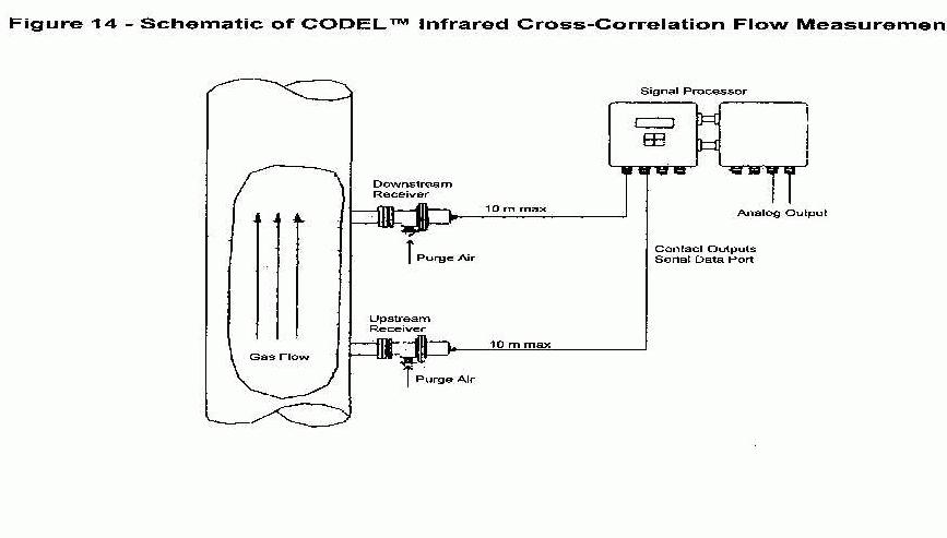
Infrared Flow Monitors
Infrared Cross-Correlation. The infrared cross-correlation flow measurement principle is different from the spectrographic velocimeter described above. This method resembles flow measurement with chemical dye or radio-active tracers, where the velocity is derived from the transport time of the tracer being added, the naturally occurring fluctuations of the infrared energy in the gas stream are used as the tracer. Hot flue gases consist of incremental volumes of distinctive infrared radiation. The incremental volumes of distinctive infrared energy remain distinguishable for a sufficient period to enable a time of flight measurement over a limited flight path. Figure 14 is a schematic of the CODEL infrared cross-correlation flow system. The CODEL flow monitor has been in used in locations in Europe: however, it is currently not used by Part 75 sources. A technical paper presented at the Acid Rain & Electric Utilities II conference in January 1997 indicated that the monitor obtained relative accuracy results less that 15% at a coal-fired utility plant. In 1997 the CODEL monitor was temporarily installed at Part 75 gas-fired and later coal-fired plants during EPA flow reference method testing and analysis field test programs; however, no test results have been made available from those test programs.
Fan Efficiency Devices
At least one company has a flow monitoring system that measures induced draft (ID) fan inlet and fan outlet gas temperatures, in conjunction with fan horsepower, to determine exhaust gas flow rates at the ID fan locations. Volumetric flow is calculated by a microprocessor included in the system, using the temperature and horsepower measurements and design data for the fan. Two potential advantages to this approach are that (1) all three measurements required to determine flow can be obtained with a high degree of accuracy, and (2) duct configurations and the presence of turbulent flow should not affect the accuracy. However, one monitor is required for each ID fan (which may result in high capital and maintenance costs). To date there are no know Part 75 sources using this technology; therefore, no long-term performance data are currently available.